| Rendering/ Caustics |
CausticsThe caustics tools of Realsoft 3D compute how light reflects from shiny and transparent objects such as glass or shiny metal around the scene. Caustics can be computed into illumination maps or rendered as a part of the ray tracing process. Magnifying GlassAdding caustics to your scene is usually easy. The first caustics tutorial about magnifying glass shows the basic steps. Tutorial level: Medium Example project: tutorprojects/rendering/mag_glass 1. Model first the required test objects:
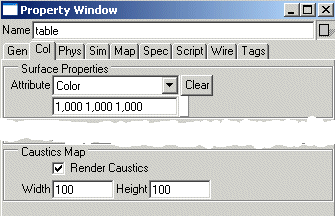
2. Then map some materials to the objects: the standard glass material to the lens and a metal (steel, chrome etc.) to other parts of the magnifying glass. In the example scene, we have added a bump map to achieve a grooved handle. The bump map is basically two dense sine wave spirals, one traveling clockwise and the other counterclockwise around the handle. The bump map is not necessary for the caustics test, but it should be noted that the grooved shiny surface will create an especially interesting light scattering in the caustics lighting. 3. Select the ground surface (table) and open the property window. Go to the 'Col' tab. Activate the 'Render Caustics' option and define a suitable caustics map resolution for the table surface - 100*100 pixels is quite OK for our simple scene.
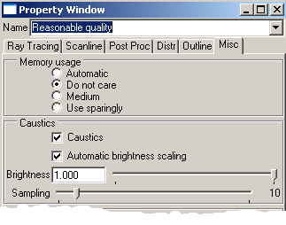
4. Before rendering, let's check the render settings. So, switch to the render settings tab of the select window and select a render settings object (for example reasonable quality). In the property window, go to the 'Ray Tracing' tab and make sure that recursion depth is at least 3, preferably 4 or 5. The higher the level, the more accurate and detailed caustics you will get. Recursion threshold should be also quite low, for example 5. Then switch to the 'Miscs' tab and make sure that the 'Caustics' and 'Automatic brightness scaling' options are set. Default maximal brightness level is 1.0 which corresponds the usual white color - it is quite appropriate. The default sampling level 10 is low but enough to get us started. Close the property window and drag&drop the edited render settings to the view window to make sure that the view will use it.
5. Start rendering. As the progress indicator messages show, the program first renders the caustics maps. Then the usual ray tracing starts. The caustics maps are placed into the 'temp' folder of Realsoft3D home directory. If your machine is not a 3 gigahertz Pentium4 system, you may have time to switch to the image tab of the select window, create an image object and use the property window to browse and view the image file named as 'temp/causticsXXX'. The program cleans up the caustics maps automatically after rendering.
That's it! You can continue experimenting with the scene - for example, double the table's caustics resolution to 200*200 pixels and increase render settings 'Sampling' value correspondingly. The result is that you will see crisper caustics patterns and finer details. A good rule of thumb is that usually 10-20 sampling units in the 'Miscs' tab of the render settings is required for every 100 pixels of caustics maps: 300 pixel caustics resolution - sampling=30, 500 pixels - sampling=50 etc. If there are several caustics targets in the scene, the maximal resolution defines what is the suitable sampling rate. Too low sampling will result to noisy caustics.
Note: Caustics illumination is attached as a texture map to target objects. A rectangle is a very efficient target because it has only one flat surface and map pixels are not wasted for the backside. Note also that a freeform object (NURBS, SDS etc) must have proper UV coordinates initialized to function properly as a caustics target.
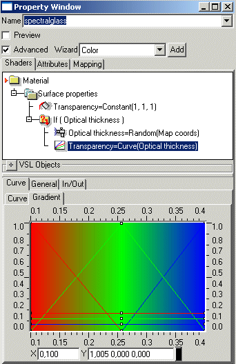
Caustics MappingThe previous tutorial explained how to use the automatic caustics rendering feature of Realsoft 3D. Now we examine how to add caustics manually to an object as an illumination map. The process is the same as when mapping indirect illumination: the UVImage tool computes the caustics map, creates required shaders and attaches them to target objects using material mapping. This method has the advantage that the caustics illumination map (and other parts of the scene) can be edited after caustics rendering. This gives additional possibilities to control the rendering process. Tutorial level: Advanced Example project: tutorprojects/rendering/spectralcaustics 1. Create a test scene: a flat analytic rectangle (floor) and a prism above the floor. Then add a point light source (a distant or spot light will also do the job) above the scene. 2. This time we will use a special kind of glass material: it processes multiple wavelengths in order to show the classical spectrum of white light which has travelled through the prism. Go to the material library, create a new VSL material called 'spectralglass' and open the property window. Define a material shown in the image below:
Let's examine the structure of the material in detail:
3. Map the spectralglass material to the prism using a parallel mapping (the Random object needs a proper 'Map coords' parameter). 4. Go to the Render settings tab of the Select window and activate for example 'Reasonable quality'. Open the property window. Go to the 'Ray Trace' tab and make sure that recursion depth is at least 3, preferably 4 or 5. Recursion Threshold should be quite low, for example 5. Then switch to the 'Misc' tab. Activate 'Caustics' option if not yet activated and turn on 'Automatic brightness scaling'. Increase the default sampling level to 20 - tracing multiple wavelengths requires lots of samples even for this simple scene. You can then close the property window. 5. Select the 'floor' rectangle from the view window. Then switch to the 'materials' tooltab and activate the UVImage tool. Set 'Type' to 'Caustics', pick the proper render settings object from the 'Settings' selector and enter a suitable file name to the 'File' gadget (for example 'textures/floorcaustics'). The default resolution of 128*128 pixels is quite OK. Hit Accept and wait until the tool finishes its job.
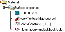
The tool adds a new material mapping object to the hierarchy and a new material to the material library. Check out the structure of the material using the property window:
The structure is quite simple. The color from the illumination map is read into a variable, then multiplied with a constant value to scale the brightness and finally added to the total illumination. You can now select the texture object and hit the 'Show' button to view the caustics map - it looks as follows:
Quite promising! Before doing the first test rendering, let's modify the scene a bit: 6. The glass material we used was quite a special one, designed for caustics purposes. It would look quite bad in normal rendering. Therefore, go to the material tab and create a 'normal' glass material if one is not yet included in the library. Then switch to the geometry tab of the select window, select the glass mapping from the hierarchy and change its target to the usual glass using the selector in the tool control bar. 7. You may also optimize the scene a bit now. Since the floor caustics already includes the 'shadow' of the prism, you may apply one of the three optimization alternatives:
8. Render the view. If the spectrum looks noisy, go to the property window, select the 'Texture' object of the caustics material and double its 'Blur' value. You can also adjust the brightness at the same time if you like. The caustics map is 'precomputed' and therefore new test renderings proceed quickly.
|
 |
 |


